FOMEI ਡਿਜੀਟਲ ਪ੍ਰੋ X ਸਟੂਡੀਓ ਫਲੈਸ਼ - PhotoRobot ਯੂਜ਼ਰ ਗਾਈਡ
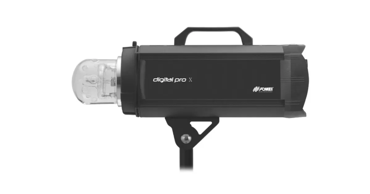
ਇਹ ਉਪਭੋਗਤਾ ਗਾਈਡ FOMEI Digital Pro X Studio Flash System ਲਈ ਮੁੱਖ ਭਾਗਾਂ ਅਤੇ ਸੰਚਾਲਨ ਨਿਰਦੇਸ਼ਾਂ ਦਾ ਵਰਣਨ ਕਰਦੀ ਹੈ। ਜਾਣਕਾਰੀ ਦਾ ਉਦੇਸ਼ PhotoRobot ਗਾਹਕਾਂ ਨੂੰ PhotoRobot ਨਾਲ Digital Pro X ਸੀਰੀਜ਼ ਸਟੂਡੀਓ ਫਲੈਸ਼ਾਂ ਦੀ ਸਥਾਪਨਾ ਅਤੇ ਵਰਤੋਂ ਵਿੱਚ ਸਹਾਇਤਾ ਕਰਨਾ ਹੈ। ਇਸ ਵਿੱਚ Digital Pro X 300, 500, ਅਤੇ 1200 ਸੀਰੀਜ਼ ਦੇ ਮੁੱਖ ਭਾਗ ਅਤੇ ਸਟੂਡੀਓ ਏਕੀਕਰਣ ਸ਼ਾਮਲ ਹਨ।
ਨੋਟ: ਇਹ ਅਸੈਂਬਲੀ ਗਾਈਡ ਅਧਿਕਾਰਤ FOMEI ਦਸਤਾਵੇਜ਼ਾਂ ਦਾ ਪ੍ਰਜਨਨ ਹੈ। PhotoRobot ਅਤੇ FOMEI PhotoRobot ਸਵੈਚਾਲਿਤ ਫੋਟੋਗ੍ਰਾਫੀ ਪ੍ਰਣਾਲੀਆਂ ਲਈ ਉਤਪਾਦ ਰੋਸ਼ਨੀ ਵਿੱਚ ਉੱਤਮਤਾ ਨੂੰ ਯਕੀਨੀ ਬਣਾਉਣ ਲਈ ਅਧਿਕਾਰਤ ਭਾਈਵਾਲ ਹਨ। ਨਿਰਮਾਤਾ ਤੋਂ ਅਧਿਕਾਰਤ ਡਾਊਨਲੋਡ ਕਰਨ ਯੋਗ PDF ਸੰਸਕਰਣ ਲਈ, FOMEI ਲਾਈਟਾਂ ਅਤੇ ਫੋਟੋਗ੍ਰਾਫੀ ਵੈੱਬਸਾਈਟ ਵੇਖੋ।
ਮਹੱਤਵਪੂਰਨ: ਕਾਰਵਾਈ ਤੋਂ ਪਹਿਲਾਂ, ਯਕੀਨੀ ਬਣਾਓ ਕਿ ਉਤਪਾਦ ਬਰਕਰਾਰ ਹੈ ਅਤੇ ਕੋਈ ਵੀ ਹਿੱਸਾ ਗੁੰਮ ਨਹੀਂ ਹੈ। ਜੇਕਰ ਕੋਈ ਨੁਕਸ ਹੈ, ਤਾਂ ਕਿਰਪਾ ਕਰਕੇ ਸਿੱਧੇ FOMEI ਨਾਲ ਸੰਪਰਕ ਕਰੋ। FOMEI ਉਤਪਾਦਾਂ ਦੀ ਵਾਰੰਟੀ ਅਤੇ ਰੱਖ-ਰਖਾਅ ਦੀ ਜਾਣਕਾਰੀ ਲਈ, ਆਪਣੀ ਡਿਵਾਈਸ ਲਈ ਵਿਸ਼ੇਸ਼ ਤੌਰ 'ਤੇ ਪ੍ਰਦਾਨ ਕੀਤੇ ਗਏ ਦਸਤਾਵੇਜ਼ਾਂ ਦਾ ਹਵਾਲਾ ਦਿਓ।
PhotoRobot - FOMEI Digital Pro X ਸੈੱਟਅੱਪ ਅਤੇ ਵਰਤੋਂ
FOMEI Digital Pro X ਸੀਰੀਜ਼ 300, 500, ਅਤੇ 1200 ਉੱਚ-ਤਕਨੀਕੀ, ਪੇਸ਼ੇਵਰ ਸਟੂਡੀਓ ਫਲੈਸ਼ ਹਨ ਜੋ PhotoRobot ਸਿਸਟਮਾਂ ਨਾਲ ਅਨੁਕੂਲ ਹਨ। ਉਨ੍ਹਾਂ ਦੇ ਵਿਲੱਖਣ, ਤੇਜ਼ ਫਲੈਸ਼ ਚਾਰਜਿੰਗ ਸਮੇਂ 360 ਅਤੇ 3D ਫੋਟੋਗ੍ਰਾਫੀ ਵਿੱਚ ਸਰਵੋਤਮ ਪ੍ਰਦਰਸ਼ਨ ਨੂੰ ਯਕੀਨੀ ਬਣਾਉਂਦੇ ਹਨ।
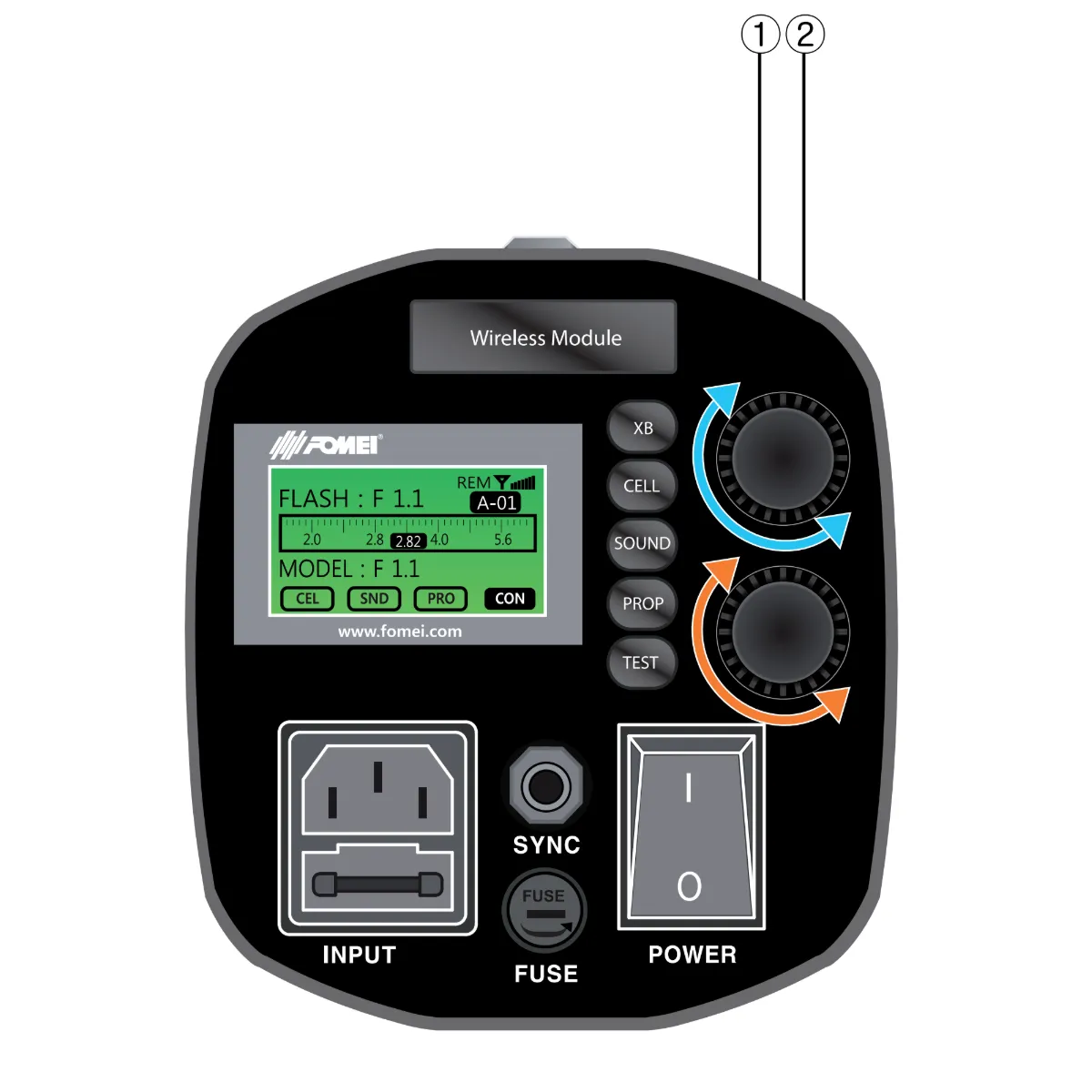
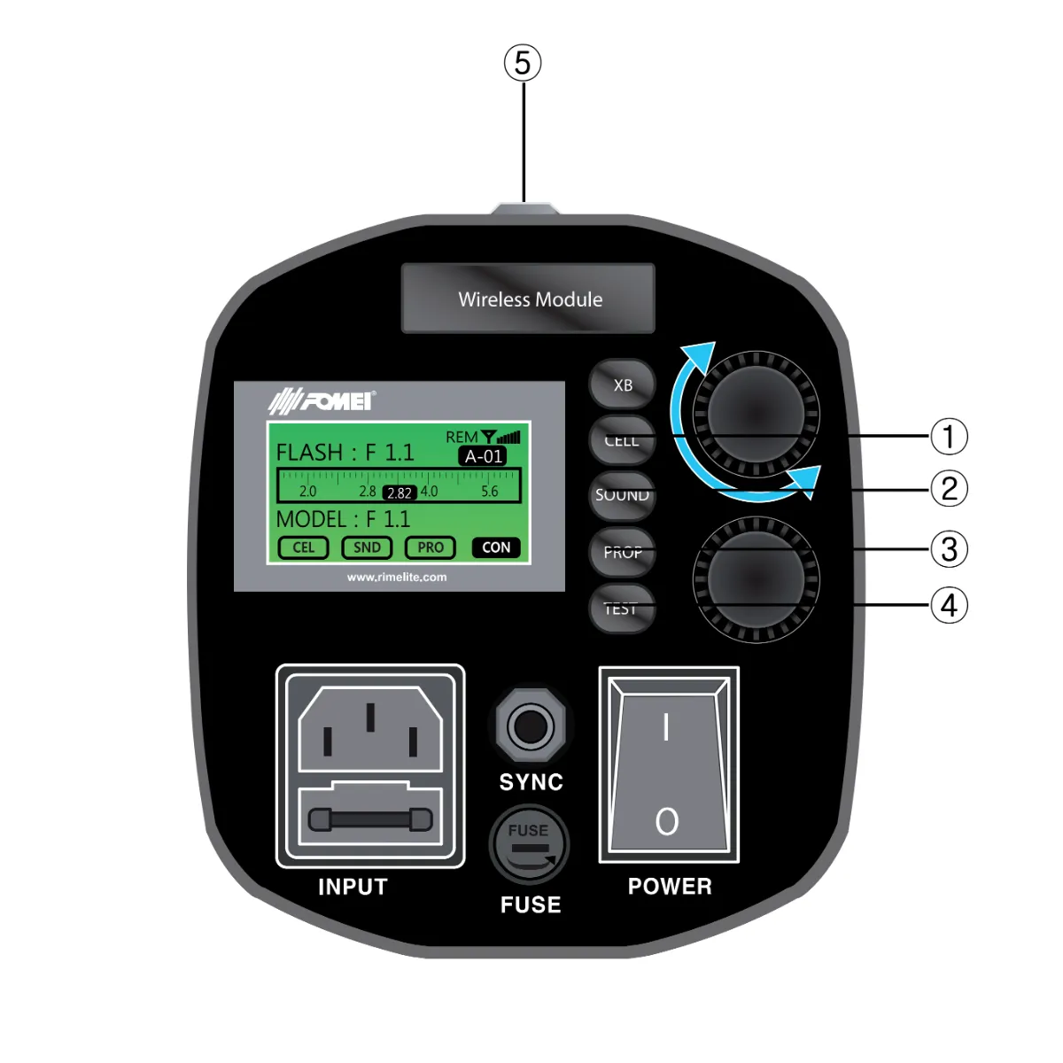
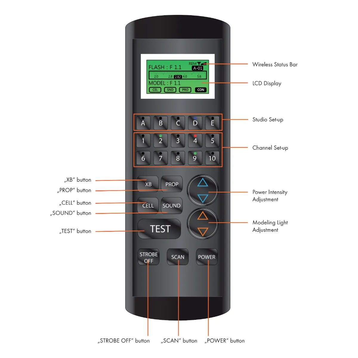
ਡਿਜੀਟਲ ਪ੍ਰੋ X ਕੰਟਰੋਲ ਅਤੇ ਡਿਸਪਲੇ
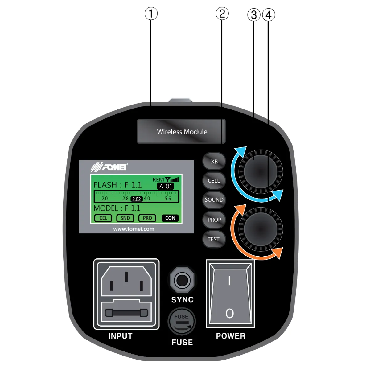
ਹੇਠਾਂ ਦਿੱਤਾ ਇਨਫੋਗ੍ਰਾਫਿਕ ਡਿਜੀਟਲ ਪ੍ਰੋ X ਕੰਟਰੋਲ ਅਤੇ ਡਿਸਪਲੇ ਦੇ ਮੁੱਖ ਭਾਗਾਂ ਦਾ ਵੇਰਵਾ ਦਿੰਦਾ ਹੈ।
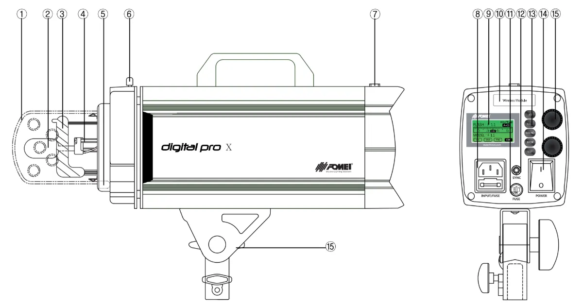
- ਕੱਚ ਦੀ ਸੁਰੱਖਿਆ
- ਮਾਡਲਿੰਗ ਲੈਂਪ
- ਫਲੈਸ਼ ਟਿਊਬ (“H“ ਨਿਸ਼ਾਨ ਦੀ ਜਾਂਚ ਕਰੋ)
- ਮਾਡਲਿੰਗ ਲੈਂਪ ਸਾਕਟ
- ਛੱਤਰੀ ਧਾਰਕ
- ਰੌਕਿੰਗ ਹੋਲਡਰ
- ਫੋਟੋਸੈੱਲ
- ਮੁੱਖ ਇਨਲੇਟ
- LCD
- ਰਿਮੋਟ ਰਿਸੀਵਰ ਹੋਲਡਰ (ਇੰਟਰਫੇਸ)
- ਮਾਡਲਿੰਗ ਲੈਂਪ ਫਿਊਜ਼
- ਸਿੰਕ ਸਾਕਟ
- ਕਾਰਜ ਬਟਨ
- ਪਾਵਰ ਚਾਲੂ/ਬੰਦ S/W
- ਪਾਵਰ ਤੀਬਰਤਾ ਉੱਪਰ/ਹੇਠਾਂ (ਡਿਜੀਟਲ ਐਨਕੋਡਰ)
- ਮਾਡਲਿੰਗ ਚਮਕ ਉੱਪਰ/ਹੇਠਾਂ (ਡਿਜੀਟਲ ਐਨਕੋਡਰ)
ਓਪਰੇਸ਼ਨ ਨਿਰਦੇਸ਼: ਇਨਫੋਗ੍ਰਾਫਿਕ 1
ਨੋਟ:
A. ਮੁੱਖ ਪਾਵਰ ਕੇਬਲ ਨੂੰ ਮੁੱਖ ਇਨਲੇਟ ਨਾਲ ਕਨੈਕਟ ਕੀਤਾ ਜਾਣਾ ਹੈ (ਪਾਵਰ S/W ਨੂੰ ਚਾਲੂ ਕਰੋ)
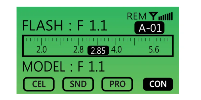
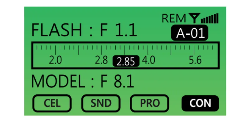
ਬੀ. ਜਦੋਂ ਚਾਲੂ ਹੁੰਦਾ ਹੈ, ਤਾਂ ਪਹਿਲੀ ਸਕ੍ਰੀਨ ਇਸ ਤਰ੍ਹਾਂ ਪ੍ਰਦਰਸ਼ਿਤ ਹੋਵੇਗੀ।
ਫਲੈਸ਼ ਪਾਵਰ ਦੀ ਤੀਬਰਤਾ ਕਿਵੇਂ ਸੈੱਟ ਕਰੀਏ (1)
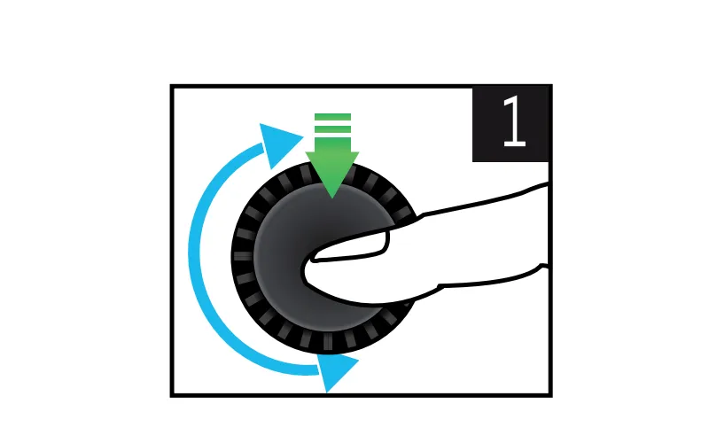
1. 0.1 F-ਸਟਾਪ ਦੁਆਰਾ ਵਧਾਓ / ਘਟਾਓ।
- ਪਾਵਰ ਇੰਟੈਂਸਿਟੀ ਵਧਾਉਣ ਲਈ ਡਿਜੀਟਲ ਐਨਕੋਡਰ ਵਾਲੀਅਮ ਨੂੰ ਸੱਜੇ ਪਾਸੇ ਮੋੜੋ।
- ਪਾਵਰ ਇੰਟੈਂਸਿਟੀ ਘਟਾਉਣ ਲਈ ਡਿਜੀਟਲ ਐਨਕੋਡਰ ਵਾਲੀਅਮ ਨੂੰ ਖੱਬੇ ਪਾਸੇ ਮੋੜੋ।
2. ਅਧਿਕਤਮ ਪਾਵਰ ਆਉਟਪੁੱਟ ਮੋਡ ਸੈੱਟ ਕਰੋ।
- ਡਾਇਲ (ਐਨਕੋਡਰ) ਨੂੰ ਸਿਰਫ਼ ਇੱਕ ਵਾਰ ਦਬਾਓ।
3. ਘੱਟੋ-ਘੱਟ ਪਾਵਰ ਆਉਟਪੁੱਟ ਮੋਡ ਸੈੱਟ ਕਰੋ।
- ਡਾਇਲ (ਐਨਕੋਡਰ) ਨੂੰ ਦੋ ਵਾਰ ਦਬਾਓ।
4. ਰੀਸਟੋਰ ਮੋਡ ਲਾਂਚ ਕਰੋ।
- ਉਪਭੋਗਤਾ ਦੁਆਰਾ ਆਖਰੀ ਪਾਵਰ ਇੰਟੈਂਸਿਟੀ ਮੁੱਲ ਨੂੰ ਬਹਾਲ ਕਰਨ ਲਈ ਡਾਇਲ (ਐਨਕੋਡਰ) ਨੂੰ ਚਾਰ ਵਾਰ ਦਬਾਓ।
ਮਾਡਲਿੰਗ ਲਾਈਟ ਵਿਸ਼ੇਸ਼ਤਾ ਦੇ ਕਾਰਜ (2)
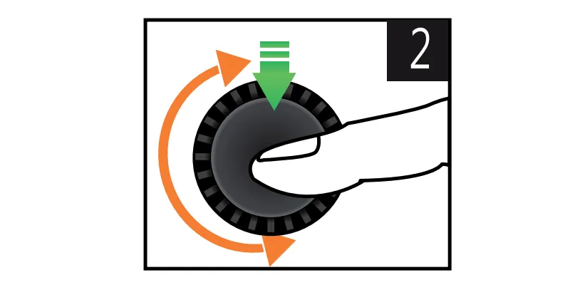
1. 0.1 F-ਸਟਾਪ (ਮਾਡਲਿੰਗ ਲਾਈਟ ਦੀ ਚਮਕ) ਦੁਆਰਾ ਵਧਾਓ / ਘਟਾਓ।
- ਮਾਡਲਿੰਗ ਲਾਈਟ ਦੀ ਚਮਕ ਵਧਾਉਣ ਲਈ ਡਿਜੀਟਲ ਐਨਕੋਡਰ ਵਾਲੀਅਮ ਨੂੰ ਸੱਜੇ ਪਾਸੇ ਮੋੜੋ।
- ਮਾਡਲਿੰਗ ਲਾਈਟ ਦੀ ਚਮਕ ਘਟਾਉਣ ਲਈ ਡਿਜੀਟਲ ਐਨਕੋਡਰ ਵਾਲੀਅਮ ਨੂੰ ਖੱਬੇ ਪਾਸੇ ਮੋੜੋ।
2. ਮਾਡਲਿੰਗ ਲਾਈਟ ਮੋਡ ਦੀ ਅਧਿਕਤਮ ਚਮਕ ਸੈੱਟ ਕਰੋ।
- ਡਾਇਲ (ਐਨਕੋਡਰ) ਨੂੰ ਸਿਰਫ਼ ਇੱਕ ਵਾਰ ਦਬਾਓ।
3. ਘੱਟੋ-ਘੱਟ ਮਾਡਲਿੰਗ ਲਾਈਟ ਮੋਡ ਸੈੱਟ ਕਰੋ।
- ਡਾਇਲ (ਐਨਕੋਡਰ) ਨੂੰ ਦੋ ਵਾਰ ਦਬਾਓ।
4. ਮਾਡਲਿੰਗ ਲਾਈਟ ਬੰਦ ਕਰੋ।
- ਡਾਇਲ (ਐਨਕੋਡਰ) ਨੂੰ ਤਿੰਨ ਵਾਰ ਦਬਾਓ।
5. ਰੀਸਟੋਰ ਮੋਡ ਲਾਂਚ ਕਰੋ।
- ਉਪਭੋਗਤਾ ਦੁਆਰਾ ਮਾਡਲਿੰਗ ਲਾਈਟ ਦੇ ਆਖਰੀ ਚਮਕ ਮੁੱਲ ਨੂੰ ਬਹਾਲ ਕਰਨ ਲਈ ਡਾਇਲ (ਐਨਕੋਡਰ) ਨੂੰ ਚਾਰ ਵਾਰ ਦਬਾਓ।
ਓਪਰੇਸ਼ਨ ਨਿਰਦੇਸ਼: ਇਨਫੋਗ੍ਰਾਫਿਕ 2

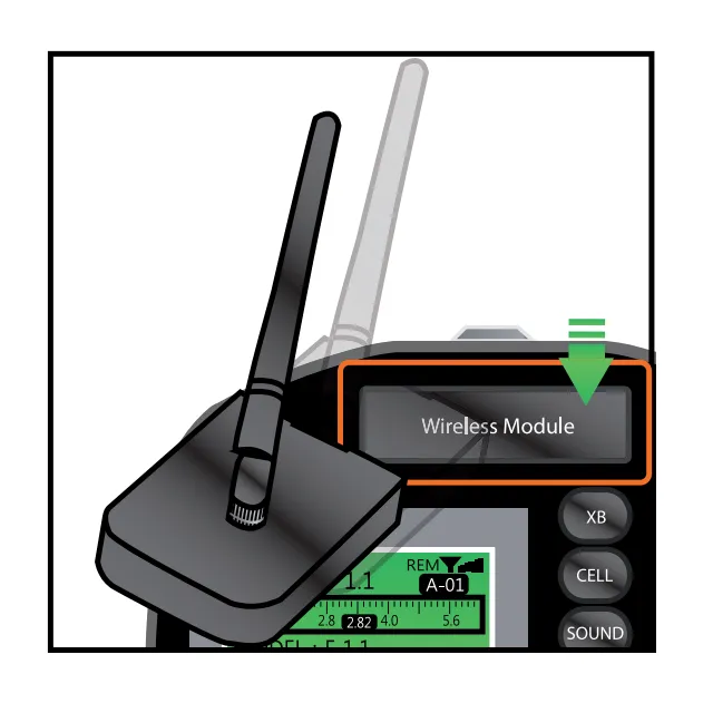
ਰਿਮੋਟ ਸਿਸਟਮ ਸੈੱਟ ਕਰਨਾ - ਵਾਇਰਲੈੱਸ ਹੋਲਡਰ (1)
ਨੋਟ:
A. ਡਿਜੀਟਲ ਪ੍ਰੋ X ਸੀਰੀਜ਼ ਫਲੈਸ਼ਾਂ ਦੇ ਸੰਚਾਲਨ ਲਈ ਰਿਮੋਟ ਕੰਟਰੋਲਰ ਅਤੇ PC ਦੁਆਰਾ ਨਿਯੰਤਰਣ ਦਾ ਸਮਰਥਨ ਕਰਨ ਲਈ ਇੱਕ ਵਾਇਰਲੈੱਸ ਰਿਸੀਵਰ ਦੀ ਲੋੜ ਹੁੰਦੀ ਹੈ।
ਬੀ. ਵਾਇਰਲੈੱਸ ਰਿਸੀਵਰ ਨੂੰ ਪਿਛਲੇ ਕਵਰ ਨਾਲ ਨੱਥੀ ਕਰੋ।
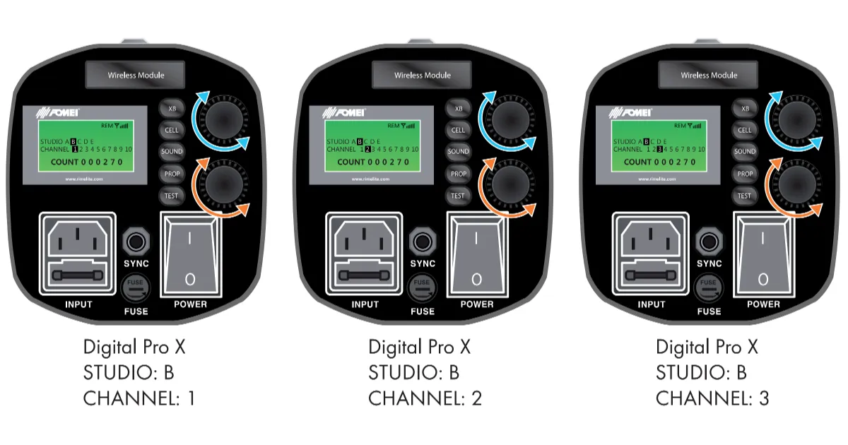
ਸਟੂਡੀਓ ਅਤੇ ਚੈਨਲ ਸਥਾਪਤ ਕਰਨਾ (2, 3, 4)
ਡਿਜੀਟਲ ਪ੍ਰੋ ਐਕਸ ਸੀਰੀਜ਼ ਵਿੱਚ ਸਟੂਡੀਓ ਅਤੇ ਚੈਨਲ ਦੋਵਾਂ ਲਈ ਮੋਡ ਹਨ।
ਨੋਟ: ਸਟੂਡੀਓ ਲਈ ਹਰੇਕ ਮੋਡ ਵਿੱਚ 10 ਸਟ੍ਰੋਬ (ਚੈਨਲ) ਹੁੰਦੇ ਹਨ।
ਉਦਾਹਰਨ ਲਈ ਇੱਕ CASE ਲਓ ਜਿਸ ਵਿੱਚ ਉਪਭੋਗਤਾ ਇੱਕੋ ਖੇਤਰ ਵਿੱਚ ਦੋ ਸਟੂਡੀਓ ਹਾਲਾਂ ਦੀ ਵਰਤੋਂ ਕਰਨਾ ਚਾਹੁੰਦਾ ਹੈ, ਅਤੇ ਹਰੇਕ ਸਟੂਡੀਓ ਵਿੱਚ ਤਿੰਨ ਡਿਜੀਟਲ ਪ੍ਰੋ X। ਇਸ CASE ਵਿੱਚ, ਇੱਕ ਗਰੁੱਪ ਨਾਮ (ਉਦਾਹਰਨ ਲਈ, “B”) ਸੈੱਟ ਕਰਨ ਲਈ ਗਰੁੱਪ ਮੋਡ ਦੀ ਵਰਤੋਂ ਕਰਨਾ ਸੰਭਵ ਹੈ, ਅਤੇ ਹਰੇਕ ਗਰੁੱਪ ਨੂੰ ਇੱਕ ਵਿਲੱਖਣ ਚੈਨਲ ਨੰਬਰ ਨਿਰਧਾਰਤ ਕਰੋ। ਹੇਠਾਂ ਦਿੱਤੀਆਂ ਤਿੰਨ ਤਸਵੀਰਾਂ ਅਤੇ ਕਦਮਾਂ ਦਾ ਹਵਾਲਾ ਦਿਓ।
1. ਸਟ੍ਰੋਬ ਗਰੁੱਪ ਦਾ ਨਾਮ ਕਿਵੇਂ ਬਦਲਣਾ ਹੈ
- ਬਟਨ “XB” ਲੱਭੋ (ਇਨਫੋਗ੍ਰਾਫਿਕ 2.2.)।
- “XB” ਬਟਨ ਨੂੰ ਦਬਾਓ ਅਤੇ ਘੱਟੋ-ਘੱਟ 3 ਸਕਿੰਟਾਂ ਲਈ ਫੜੀ ਰੱਖੋ।
- ਇੱਕ ਗਰੁੱਪ ਨਾਮ ਬਦਲਣ ਲਈ ਮੋਡ ਦ੍ਰਿਸ਼ LCD ਸਕ੍ਰੀਨ 'ਤੇ ਪ੍ਰਦਰਸ਼ਿਤ ਹੋਵੇਗਾ।
- ਗਰੁੱਪ ਨਾਮ ਬਦਲਣ ਲਈ, ਡਾਇਲ (ਇਨਫੋਗ੍ਰਾਫਿਕ 2.3.) ਨੂੰ ਨਾਮਾਂ ਨੂੰ ਸਕ੍ਰੋਲ ਕਰਨ ਲਈ ਸੱਜੇ ਜਾਂ ਖੱਬੇ ਪਾਸੇ ਘੁਮਾਓ, ਅਤੇ ਗਰੁੱਪ ਦੀ ਚੋਣ ਦੀ ਪੁਸ਼ਟੀ ਕਰਨ ਲਈ “XB” ਬਟਨ ਨੂੰ ਇੱਕ ਵਾਰ ਫਿਰ ਥੋੜ੍ਹੇ ਸਮੇਂ ਲਈ ਦਬਾਓ।
2. ਸਟ੍ਰੋਬ ਚੈਨਲ ਨੰਬਰ ਕਿਵੇਂ ਬਦਲਣਾ ਹੈ
- “XB” ਬਟਨ ਦੀ ਵਰਤੋਂ ਕਰੋ (ਇਨਫੋਗ੍ਰਾਫਿਕ 2.2.)।
- “XB” ਬਟਨ ਨੂੰ ਦਬਾਓ ਅਤੇ ਘੱਟੋ-ਘੱਟ 3 ਸਕਿੰਟਾਂ ਲਈ ਫੜੀ ਰੱਖੋ।
- ਗਰੁੱਪ ਦਾ ਨਾਮ ਬਦਲਣ ਲਈ ਮੋਡ ਦ੍ਰਿਸ਼ LCD ਡਿਸਪਲੇ 'ਤੇ ਦਿਖਾਈ ਦੇਵੇਗਾ।
- ਚੈਨਲ ਨੰਬਰ ਬਦਲਣ ਲਈ, ਡਾਇਲ (ਇਨਫੋਗ੍ਰਾਫਿਕ 2.4.) ਨੂੰ ਚੈਨਲ ਨੰਬਰਾਂ ਨੂੰ ਸਕ੍ਰੋਲ ਕਰਨ ਲਈ ਸੱਜੇ ਜਾਂ ਖੱਬੇ ਪਾਸੇ ਘੁਮਾਓ, ਅਤੇ ਚੈਨਲ ਚੋਣ ਦੀ ਪੁਸ਼ਟੀ ਕਰਨ ਲਈ “XB” ਬਟਨ ਨੂੰ ਇੱਕ ਵਾਰ ਫਿਰ ਥੋੜ੍ਹੇ ਸਮੇਂ ਲਈ ਦਬਾਓ।
ਓਪਰੇਸ਼ਨ ਨਿਰਦੇਸ਼: ਇਨਫੋਗ੍ਰਾਫਿਕ 3
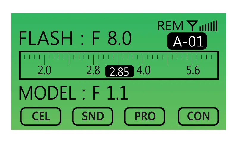
ACS (Aperture Control System) ਨੂੰ ਕਿਵੇਂ ਸੈੱਟ ਕਰੀਏ
ਨੋਟ ਕਰੋ ਕਿ Digital Pro X ਵਿੱਚ ਸ਼ੁਰੂਆਤੀ ਐਕਸਪੋਜ਼ਰ ਮੁੱਲ ਸੈੱਟ ਕਰਨ ਤੋਂ ਬਾਅਦ, ਡਿਵਾਈਸ ਬਾਹਰੀ ਐਕਸਪੋਜ਼ਰ ਮੀਟਰ ਦੀ ਲੋੜ ਤੋਂ ਬਿਨਾਂ ਸਹੀ ਐਕਸਪੋਜ਼ਰ ਐਡਜਸਟਮੈਂਟ ਦੀ ਇਜਾਜ਼ਤ ਦਿੰਦਾ ਹੈ। ਇਹ ਉਪਭੋਗਤਾ ਨੂੰ ਡਿਵਾਈਸ ਨਿਯੰਤਰਣਾਂ ਅਤੇ LCD ਡਿਸਪਲੇਅ ਦੀ ਵਰਤੋਂ ਕਰਕੇ ਕਿਸੇ ਵੀ ਸਮੇਂ ਐਕਸਪੋਜ਼ਰ ਮੁੱਲ ਨੂੰ ਵਧਾਉਣ ਜਾਂ ਘਟਾਉਣ ਦੇ ਯੋਗ ਬਣਾਉਂਦਾ ਹੈ। LCD ਡਿਸਪਲੇਅ ਸਹੀ ਐਕਸਪੋਜ਼ਰ ਮੁੱਲ ਦਿਖਾਉਂਦਾ ਹੈ, ਜਦੋਂ ਕਿ ਪ੍ਰਦਰਸ਼ਿਤ ਮੁੱਲ ਉਦੋਂ ਤੱਕ ਸਹੀ ਰਹਿੰਦਾ ਹੈ ਜਦੋਂ ਤੱਕ ਵਿਸ਼ੇ, ਕੈਮਰਾ ਅਤੇ Digital Pro X ਵਿਚਕਾਰ ਸਾਪੇਖਿਕ ਸਥਿਤੀਆਂ ਅਤੇ ਦੂਰੀਆਂ ਬਦਲੀਆਂ ਨਹੀਂ ਰਹਿੰਦੀਆਂ।
1. ACS ਦੀ ਜਾਂਚ ਕਿਵੇਂ ਕਰੀਏ
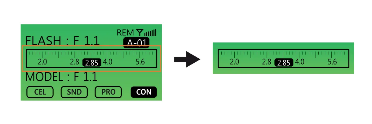
- LCD ਡਿਸਪਲੇਅ ਮੌਜੂਦਾ ACS ਸਥਿਤੀ ਨੂੰ ਦਰਸਾਉਂਦਾ ਹੈ।
- ਜਦੋਂ ACS ਸਟੈਂਡਬਾਏ ਮੋਡ ਵਿੱਚ ਹੁੰਦਾ ਹੈ, ਤਾਂ ਇਹ ਸਥਿਤੀ ਸਕ੍ਰੀਨ 'ਤੇ ਦਿਖਾਈ ਜਾਂਦੀ ਹੈ।
2. ACS ਨੂੰ ਕਿਵੇਂ ਰੀਸੈਟ ਕਰੀਏ
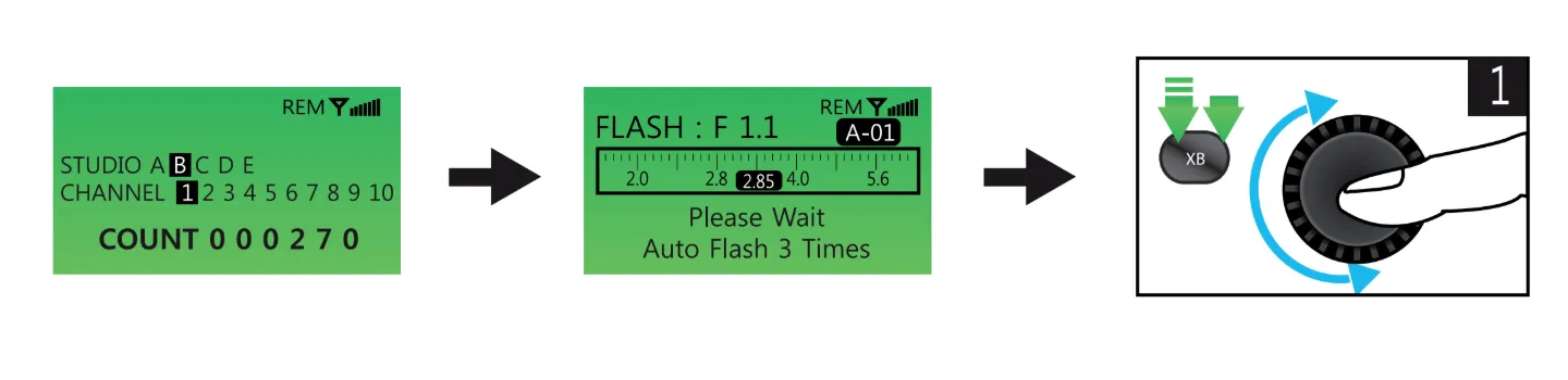
- “XB” ਬਟਨ (ਇਨਫੋਗ੍ਰਾਫਿਕ 3.2.) ਨੂੰ ਦਬਾਓ ਅਤੇ ਘੱਟੋ-ਘੱਟ 3 ਸਕਿੰਟਾਂ ਲਈ ਫੜੀ ਰੱਖੋ – LCD ਹੇਠਾਂ ਦਿੱਤੀ ਤਸਵੀਰ (ਖੱਬੇ) ਪ੍ਰਦਰਸ਼ਿਤ ਕਰੇਗਾ।
- “XB” ਬਟਨ ਨੂੰ ਇੱਕ ਵਾਰ ਹੋਰ ਦਬਾਓ – LCD ਵਿੰਡੋ ਹੇਠਾਂ ਦਿੱਤੀ ਤਸਵੀਰ (ਕੇਂਦਰ) ਨੂੰ ਪ੍ਰਦਰਸ਼ਿਤ ਕਰੇਗੀ।
- ਡਾਇਲ (ਇਨਫੋਗ੍ਰਾਫਿਕ 3.3.) ਨੂੰ ਸੱਜੇ ਜਾਂ ਖੱਬੇ ਮੋੜ ਕੇ, ਉਪਭੋਗਤਾ ਸਹੀ ਡੇਟਾ ਨਾਲ ਐਕਸਪੋਜ਼ਰ ਮੁੱਲ ਨੂੰ ਰੀਸੈਟ ਕਰ ਸਕਦਾ ਹੈ। ਹਾਲਾਂਕਿ, ਇਸ ਫੰਕਸ਼ਨ ਦੀ ਵਰਤੋਂ ਕਰਨ ਲਈ, ਉਪਭੋਗਤਾ ਨੂੰ ਪਹਿਲਾਂ ਐਕਸਪੋਜ਼ਰ ਮੀਟਰ ਦੀ ਵਰਤੋਂ ਕਰਕੇ ਸਹੀ ਐਕਸਪੋਜ਼ਰ ਮੁੱਲ ਦੀ ਜਾਂਚ ਕਰਨੀ ਪਵੇਗੀ।
- ਐਕਸਪੋਜ਼ਰ ਮੀਟਰ ਨਾਲ ਐਕਸਪੋਜ਼ਰ ਮੁੱਲ ਦੀ ਜਾਂਚ ਕਰਨ ਤੋਂ ਬਾਅਦ, ਉਪਭੋਗਤਾ ਸਹੀ ਐਕਸਪੋਜ਼ਰ ਮੁੱਲ ਨੂੰ Digital Pro X ਵਿੱਚ ਦਾਖਲ ਕਰਦਾ ਹੈ। ਫਿਰ, ਉਪਭੋਗਤਾ ਨੂੰ ਐਕਸਪੋਜ਼ਰ ਮੀਟਰ ਦੀ ਵਰਤੋਂ ਕਰਨ ਦੀ ਲੋੜ ਨਹੀਂ ਪਵੇਗੀ ਜਦੋਂ ਤੱਕ ਵਿਸ਼ੇ, ਕੈਮਰੇ ਅਤੇ Digital Pro X ਵਿਚਕਾਰ ਸਾਪੇਖਿਕ ਸਥਿਤੀਆਂ ਅਤੇ ਦੂਰੀਆਂ ਬਦਲੀਆਂ ਨਹੀਂ ਰਹਿੰਦੀਆਂ।
3. ਸਹੀ ਐਕਸਪੋਜ਼ਰ ਮੁੱਲ ਕਿਵੇਂ ਇਨਪੁਟ ਕਰੀਏ
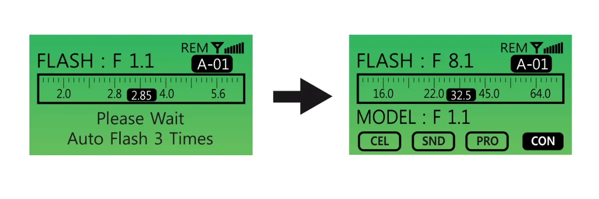
- ਉਪਭੋਗਤਾ ਨੂੰ Digital Pro X ਵਿੱਚ ਸਹੀ ਐਕਸਪੋਜ਼ਰ ਮੁੱਲ ਦਰਜ ਕਰਨਾ ਚਾਹੀਦਾ ਹੈ ਜਦੋਂ ਇਸਦੀ Power Intensity (F-stop) F1.1 ਹੋਵੇ।
- ਡਾਇਲ (ਇਨਫੋਗ੍ਰਾਫਿਕ 3.3.) ਨੂੰ ਸੱਜੇ ਜਾਂ ਖੱਬੇ ਮੋੜ ਕੇ ਐਕਸਪੋਜ਼ਰ ਮੁੱਲ ਚੁਣੋ।
- “XB” ਬਟਨ ਨੂੰ ਦੋ ਵਾਰ ਦਬਾਉਣ ਤੋਂ ਬਾਅਦ ਐਕਸਪੋਜ਼ਰ ਮੁੱਲ ਦਰਜ ਕਰੋ।
- ਉਦਾਹਰਨ ਲਈ, ਉਪਰੋਕਤ ਚਿੱਤਰਾਂ ਨੂੰ ਵੇਖੋ।
ਜੇਕਰ ਮਾਪਿਆ ਗਿਆ ਐਕਸਪੋਜ਼ਰ ਮੁੱਲ 32.5 i-stop ਹੈ, ਤਾਂ ਇਸ ਮੁੱਲ ਨੂੰ Digital Pro X ਵਿੱਚ ਦਾਖਲ ਕਰੋ। ਇੱਕ ਵਾਰ ਐਕਸਪੋਜ਼ਰ ਮੁੱਲ ਸੈੱਟ ਹੋ ਜਾਣ ਤੋਂ ਬਾਅਦ, ਬਾਅਦ ਦੀਆਂ ਤਸਵੀਰਾਂ ਲਈ ਬਾਹਰੀ ਐਕਸਪੋਜ਼ਰ ਮੀਟਰ ਦੀ ਵਰਤੋਂ ਕੀਤੇ ਬਿਨਾਂ ਡਿਵਾਈਸ 'ਤੇ ਸਿੱਧੇ ਹੋਰ ਐਕਸਪੋਜ਼ਰ ਐਡਜਸਟਮੈਂਟ ਕੀਤੇ ਜਾ ਸਕਦੇ ਹਨ।
ਓਪਰੇਸ਼ਨ ਨਿਰਦੇਸ਼: ਇਨਫੋਗ੍ਰਾਫਿਕ 4
ਹੋਰ ਫੰਕਸ਼ਨ
1. ਫੋਟੋ ਸੈੱਲ ਚਾਲੂ / ਬੰਦ
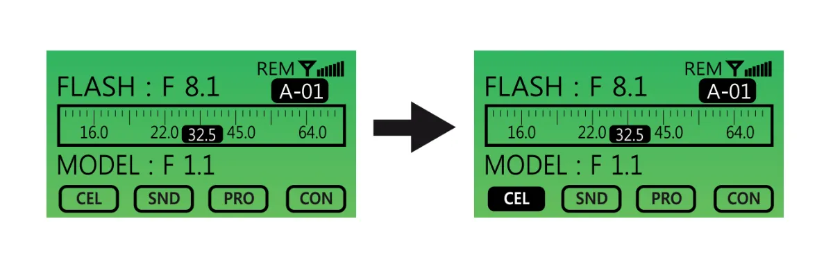
- CELL ਬਟਨ ਨੂੰ ਇੱਕ ਵਾਰ ਦਬਾਓ। ਜਦੋਂ LCD ਡਿਸਪਲੇ 'ਤੇ "CELL" ਆਈਕਨ ਇੱਕ ਠੋਸ ਬੈਕਗ੍ਰਾਉਂਡ (ਕਾਲੇ ਰੰਗ ਵਿੱਚ ਭਰਿਆ ਹੋਇਆ) ਨਾਲ ਹਾਈਲਾਈਟ ਹੁੰਦਾ ਹੈ, ਤਾਂ Photo Cell ਫੰਕਸ਼ਨ ਕਿਰਿਆਸ਼ੀਲ ਹੁੰਦਾ ਹੈ। ਫੰਕਸ਼ਨ ਨੂੰ ਅਕਿਰਿਆਸ਼ੀਲ ਕਰਨ ਲਈ, CELL ਬਟਨ ਨੂੰ ਇੱਕ ਵਾਰ ਹੋਰ ਦਬਾਓ।
2. ਆਵਾਜ਼ ਚਾਲੂ / ਬੰਦ
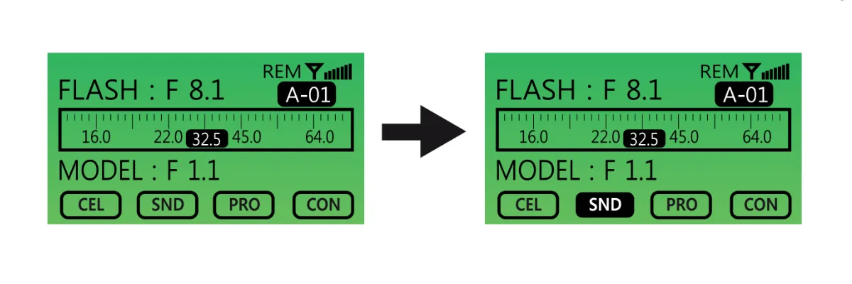
- ਚਾਲੂ ਕਰਨ ਲਈ SOUND (“SND”) ਬਟਨ ਨੂੰ ਇੱਕ ਵਾਰ ਦਬਾਓ। ਜਦੋਂ ਕਿਰਿਆਸ਼ੀਲ ਹੋਵੇ, “SND” ਆਈਕਨ ਹਾਈਲਾਈਟ ਹੋ ਜਾਵੇਗਾ। ਇਸਨੂੰ ਅਕਿਰਿਆਸ਼ੀਲ ਕਰਨ ਲਈ, SOUND ਬਟਨ ਨੂੰ ਇੱਕ ਵਾਰ ਹੋਰ ਦਬਾਓ।
3. ਅਨੁਪਾਤਕ (PROP) ਮਾਡਲਿੰਗ ਲਾਈਟ
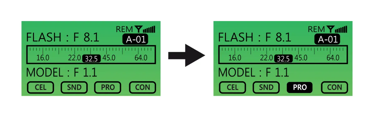
- ਬਟਨ ਨੂੰ ਇੱਕ ਵਾਰ ਦਬਾ ਕੇ ਪ੍ਰੋਪੋਰਸ਼ਨਲ (PROP) ON / OFF ਮਾਡਲਿੰਗ ਲਾਈਟ ਸੈਟਿੰਗ ਨੂੰ ਚਾਲੂ ਕਰੋ, ਅਤੇ ਦੁਬਾਰਾ ਦਬਾ ਕੇ ਬੰਦ ਕਰੋ। ਜਦੋਂ ਕਿਰਿਆਸ਼ੀਲ ਹੁੰਦਾ ਹੈ, PROP ਬਟਨ ਇੱਕ ਗੂੜ੍ਹੇ ਬੈਕਗ੍ਰਾਉਂਡ ਨਾਲ ਹਾਈਲਾਈਟ ਕੀਤਾ ਜਾਵੇਗਾ।
4. ਲਗਾਤਾਰ ਮਾਡਲਿੰਗ ਲਾਈਟ ਚਾਲੂ / ਬੰਦ
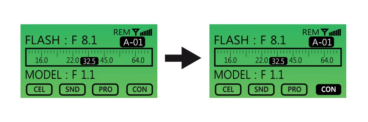
- ਲਗਾਤਾਰ ਮਾਡਲਿੰਗ ਲਾਈਟ ਨੂੰ ਚਾਲੂ / ਬੰਦ ਕਰਨ ਲਈ CONTINUOUS (CON) ਬਟਨ ਦੀ ਵਰਤੋਂ ਕਰੋ। ਬਟਨ ਦੀ ਕਾਰਗੁਜ਼ਾਰੀ ਉਪਰੋਕਤ ਵਾਂਗ ਹੀ ਹੈ।
4. ਟੈਸਟ ਬਟਨ
- ਫਲੈਸ਼ ਟਿਊਬ ਡਿਸਚਾਰਜ ਹੋ ਗਈ ਹੈ ਜਾਂ ਨਹੀਂ, ਇਹ ਜਾਂਚਣ ਲਈ TEST ਬਟਨ ਦੀ ਵਰਤੋਂ ਕਰੋ।
ਰਿਮੋਟ ਕੰਟਰੋਲਰ ਨੂੰ ਕਿਵੇਂ ਸੈੱਟ ਕਰਨਾ ਹੈ
ਨੋਟ:
A. ਰਿਮੋਟ ਕੰਟਰੋਲਰ 'ਤੇ ਜ਼ਿਆਦਾਤਰ ਨਿਯੰਤਰਣ Digital Pro X ਦੇ ਨਿਯੰਤਰਣਾਂ ਵਾਂਗ ਹੀ ਕੰਮ ਕਰਦੇ ਹਨ।
ਬੀ. ਡਿਜੀਟਲ ਪ੍ਰੋ ਐਕਸ ਅਤੇ ਰਿਮੋਟ ਕੰਟਰੋਲਰ ਵਿਚਕਾਰ ਸਿਰਫ਼ ਕੁਝ ਹੀ ਨਿਯੰਤਰਣ ਵੱਖਰੇ ਹਨ।
1. “XB” ਬਟਨ
- “XB” ਬਟਨ ਦਾ ਪਹਿਲਾ ਕਾਰਜ ਹਰੇਕ ਸਟ੍ਰੋਬ (ਚੈਨਲ) ਦੀ ਗਤੀਵਿਧੀ ਲਈ ਹੈ।
- ਹਰੇਕ ਸਟ੍ਰੋਬ (ਚੈਨਲ) ਲਈ ਫੰਕਸ਼ਨਾਂ ਨੂੰ ਐਡਜਸਟ ਕਰਨ ਲਈ, ਪਹਿਲਾਂ ਐਡਜਸਟ ਕੀਤੇ ਜਾਣ ਵਾਲੇ ਸਟ੍ਰੋਬ ਨੂੰ ਚੁਣੋ, ਅਤੇ ਫਿਰ “XB” ਬਟਨ ਦਬਾਓ। ਇਹ ਸਟ੍ਰੋਬ (ਚੈਨਲ) ਦੇ ਫੰਕਸ਼ਨਾਂ ਨੂੰ ਐਡਜਸਟ ਕਰਨ ਦੀ ਇਜਾਜ਼ਤ ਦੇਵੇਗਾ।
- “XB” ਬਟਨ ਦਾ ਦੂਜਾ ਫੰਕਸ਼ਨ ACS ਮੋਡ ਹੈ। ACS ਮੋਡ ਨੂੰ ਐਕਟੀਵੇਟ ਕਰਨ ਲਈ XB ਬਟਨ ਨੂੰ 3 ਸਕਿੰਟਾਂ ਲਈ ਦਬਾ ਕੇ ਰੱਖੋ। ACS ਮੋਡ ਵਿੱਚ, ਫਲੈਸ਼ ਆਉਟਪੁੱਟ ਨੂੰ 0.1 f-stop ਵਾਧੇ ਵਿੱਚ ਐਡਜਸਟ ਕੀਤਾ ਜਾ ਸਕਦਾ ਹੈ।
2. “CELL” ਬਟਨ
- ਫੋਟੋਸੈੱਲ ਚਾਲੂ / ਬੰਦ ਕਰੋ
3. “SND” ਬਟਨ
- ਆਵਾਜ਼ ਚਾਲੂ / ਬੰਦ ਕਰੋ
4. “PROP” ਬਟਨ
- ਪਾਵਰ ਇੰਟੈਂਸਿਟੀ ON / FREE ਨਾਲ ਅਨੁਪਾਤਕ ਮਾਡਲਿੰਗ ਲਾਈਟ ਨੂੰ ਬਦਲਣ ਲਈ “PROP” ਬਟਨ ਨੂੰ ਦਬਾਓ ਅਤੇ ਸੰਖੇਪ ਵਿੱਚ ਫੜੀ ਰੱਖੋ।
- ਅਨੁਪਾਤਕ ਮਾਡਲਿੰਗ ਲਾਈਟ ਕੰਟੀਨਿਊਸ ON / OFF ਨੂੰ ਬਦਲਣ ਲਈ “PROP” ਨੂੰ ਘੱਟੋ-ਘੱਟ 2 ਸਕਿੰਟਾਂ ਲਈ ਦਬਾਓ ਅਤੇ ਫੜੀ ਰੱਖੋ।
5. “ਟੈਸਟ” ਬਟਨ
- ਫਲੈਸ਼ ਟਿਊਬ ਡਿਸਚਾਰਜ ਹੋ ਗਈ ਹੈ ਜਾਂ ਨਹੀਂ, ਇਹ ਜਾਂਚਣ ਲਈ “TEST” ਬਟਨ ਦਬਾਓ।
6. “STROBE OFF” ਬਟਨ
- ਸਟ੍ਰੋਬ ਦੀ ਪਾਵਰ s/w ON / OFF ਦੀ ਸਥਿਤੀ ਬਦਲਣ ਲਈ “STROBE OFF” ਬਟਨ ਦੀ ਵਰਤੋਂ ਕਰੋ।
- ਇੱਕ ਸਟ੍ਰੋਬ ਚੁਣੋ ਅਤੇ ਚਾਲੂ/ਬੰਦ ਕਰਨ ਲਈ “STROBE OFF” ਦਬਾਓ।
- ਉਦਾਹਰਨ ਲਈ, ਇੱਕ ਡਿਜੀਟਲ ਪ੍ਰੋ X ਫਲੈਸ਼ ਨੂੰ ਚਾਲੂ/ਬੰਦ ਕਰਨ ਲਈ, ਪਹਿਲਾਂ ਨਾਮ ਦੁਆਰਾ GROUP (ਸਟੂਡੀਓ) ਚੁਣੋ (ਭਾਵ “ਗਰੁੱਪ A”), ਫਿਰ ਚੈਨਲ ਨੰਬਰ ਚੁਣੋ, ਅਤੇ ਅੰਤ ਵਿੱਚ ਗਰੁੱਪ ਅਤੇ ਚੈਨਲ ਨੂੰ ਚਾਲੂ/ਬੰਦ ਕਰਨ ਲਈ “STROBE OFF” ਦੀ ਵਰਤੋਂ ਕਰੋ।
7. “SCAN” ਬਟਨ
- ਰਿਮੋਟ ਕੰਟਰੋਲਰ ਨਾਲ ਜੁੜੇ ਸਟ੍ਰੋਬਾਂ ਦੀ ਕੁੱਲ ਸੰਖਿਆ ਨੂੰ ਸਕੈਨ ਕਰਨ ਲਈ “SCAN” ਬਟਨ ਦਬਾਓ।
8. “POWER” ਬਟਨ
- ਰਿਮੋਟ ਕੰਟਰੋਲਰ ਨੂੰ ਚਾਲੂ ਕਰਨ ਲਈ “POWER” ਦਬਾਓ।
- ਨੋਟ: ਰਿਮੋਟ ਦੀ ਪਾਵਰ 1 ਮਿੰਟ ਦੀ ਕੋਈ ਗਤੀਵਿਧੀ ਨਾ ਹੋਣ ਤੋਂ ਬਾਅਦ ਆਪਣੇ ਆਪ ਬੰਦ ਹੋ ਜਾਵੇਗੀ।
ਡਿਜੀਟਲ ਪ੍ਰੋ X ਡਰਾਈਵਰ ਨੂੰ ਕਿਵੇਂ ਸਥਾਪਿਤ ਕਰੀਏ
ਡਿਜੀਟਲ ਪ੍ਰੋ X ਸੀਰੀਜ਼ ਫਲੈਸ਼ਾਂ ਲਈ ਡਰਾਈਵਰ ਇੰਸਟਾਲੇਸ਼ਨ ਦੌਰਾਨ, ਹੇਠ ਲਿਖੀਆਂ ਗੱਲਾਂ ਦਾ ਧਿਆਨ ਰੱਖੋ।
A. ਡਿਜੀਟਲ ਪ੍ਰੋ X ਡਰਾਈਵਰ ਦੇ ਜ਼ਿਆਦਾਤਰ ਬੁਨਿਆਦੀ ਫੰਕਸ਼ਨ ਡਿਜੀਟਲ ਪ੍ਰੋ X ਡਿਵਾਈਸ ਦੇ ਫੰਕਸ਼ਨਾਂ ਦੇ ਸਮਾਨ ਹਨ।
ਬੀ. ਡਰਾਈਵਰ ਅਤੇ ਡਿਵਾਈਸ ਵਿਚਕਾਰ ਸਿਰਫ਼ ਕੁਝ ਫੰਕਸ਼ਨ ਹੀ ਵੱਖਰੇ ਹੁੰਦੇ ਹਨ।
1. ਓਪਰੇਟਿੰਗ ਪ੍ਰੋਗਰਾਮ ਦੀ ਸਥਾਪਨਾ ਸ਼ੁਰੂ ਕਰੋ।
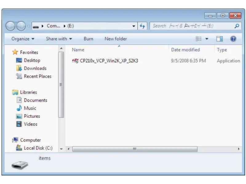
- ਇੰਸਟਾਲੇਸ਼ਨ ਸ਼ੁਰੂ ਕਰਨ ਲਈ CP210x_VCP_Win2K_XP_S2K3.exe 'ਤੇ ਡਬਲ-ਕਲਿੱਕ ਕਰੋ।
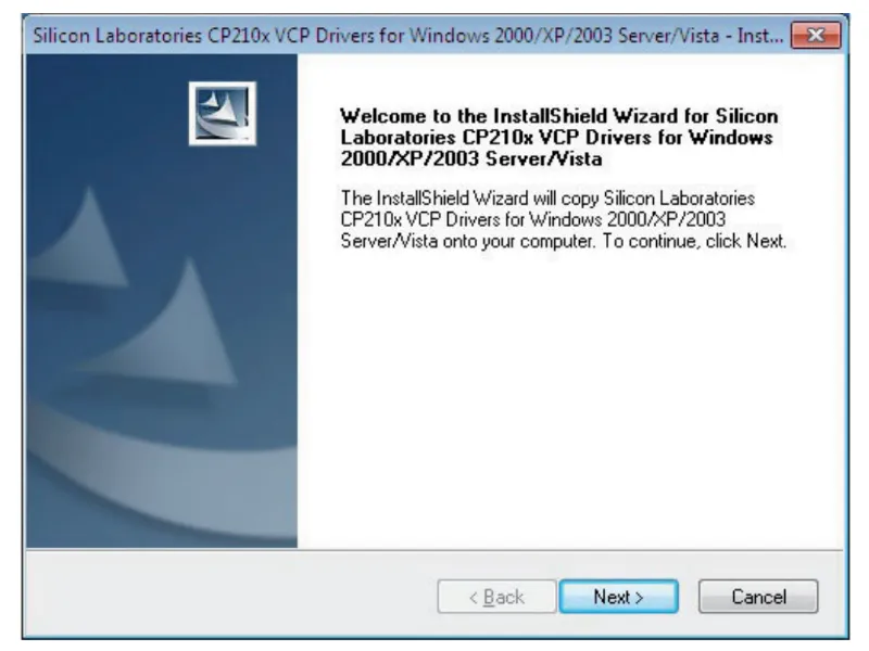
2. “ਅੱਗੇ” 'ਤੇ ਕਲਿੱਕ ਕਰੋ ਇੰਸਟਾਲੇਸ਼ਨ ਪ੍ਰਕਿਰਿਆ ਜਾਰੀ ਰੱਖਣ ਲਈ।
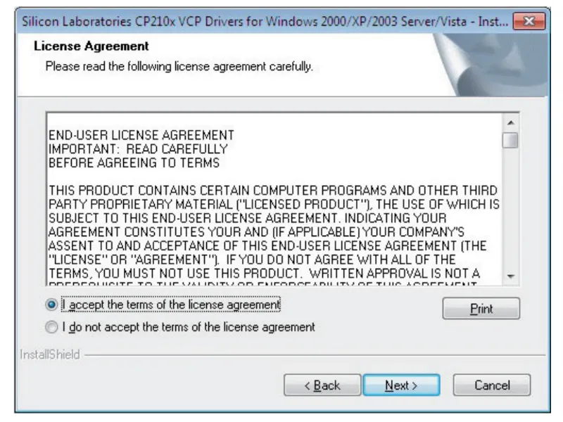
3. ਲਾਇਸੈਂਸ ਸਮਝੌਤੇ ਦੀਆਂ ਸ਼ਰਤਾਂ ਪੜ੍ਹੋ ਅਤੇ ਸਵੀਕਾਰ ਕਰੋ, ਅਤੇ ਦੁਬਾਰਾ “ਅੱਗੇ” 'ਤੇ ਕਲਿੱਕ ਕਰੋ।
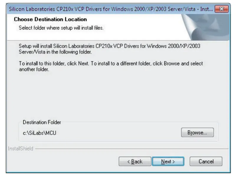
4. ਪ੍ਰੋਗਰਾਮ ਨੂੰ ਸਥਾਪਤ ਕਰਨ ਲਈ ਮੰਜ਼ਿਲ ਫੋਲਡਰ ਚੁਣੋ, ਅਤੇ “ਅੱਗੇ” 'ਤੇ ਕਲਿੱਕ ਕਰੋ।
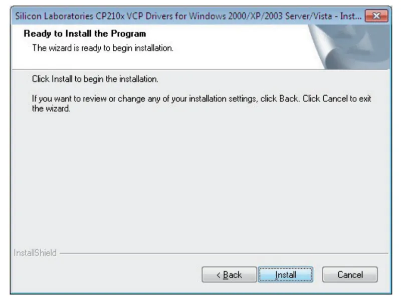
5. ਇੰਸਟਾਲੇਸ਼ਨ ਵਿਜ਼ਾਰਡ ਨੂੰ ਲਾਂਚ ਕਰਨ ਲਈ “ਇੰਸਟਾਲ” 'ਤੇ ਕਲਿੱਕ ਕਰੋ।
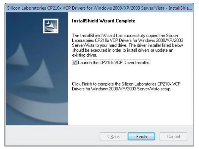
6. “Launch the CP2l0x VCP Driver Installer” ਬਾਕਸ ਨੂੰ ਚੈੱਕ ਕਰੋ ਅਤੇ “Finish” 'ਤੇ ਕਲਿੱਕ ਕਰੋ।
7. ਸਫਲ ਡਾਊਨਲੋਡ ਤੋਂ ਬਾਅਦ, ਜਾਂਚ ਕਰੋ ਕਿ ਕੀ “Silicon Labs CP210 x USB to UART Bridge (COM 3)” ਤੁਹਾਡੇ ਕੰਪਿਊਟਰ ਦੇ ਡਿਵਾਈਸ ਮੈਨੇਜਰ 'ਤੇ ਸਥਾਪਿਤ ਹੈ।
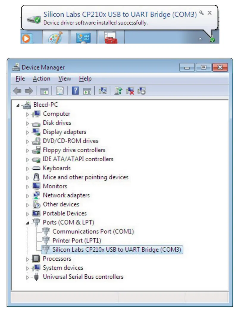
- ਮੇਰੇ ਕੰਪਿਊਟਰ > ਕੰਟਰੋਲ ਪੈਨਲ > ਡਿਵਾਈਸ ਮੈਨੇਜਰ > “PORTS (COM & LPT)” 'ਤੇ ਕਲਿੱਕ ਕਰੋ ਰਾਹੀਂ ਜਾਂਚ ਕਰੋ
8. “ਲਾਈਟਸ ਐਕਸਟੈਂਡਡ” ਪ੍ਰੋਗਰਾਮ ਚਲਾਓ ਅਤੇ ਲਾਈਟਸ ਐਕਸਟੈਂਡਡ ਆਈਕਨ 'ਤੇ ਕਲਿੱਕ ਕਰੋ।
- “ਲਾਈਟਸ ਐਕਸਟੈਂਡਡ” ਆਈਕਨ ਇੰਟਰਫੇਸ ਦੇ ਉੱਪਰ-ਖੱਬੇ ਮੀਨੂ ਵਿੱਚ ਸਥਿਤ ਹੈ। ਇੱਕ ਪੌਪ-ਅੱਪ ਵਿੰਡੋ ਖੋਲ੍ਹਣ ਲਈ ਆਈਕਨ 'ਤੇ ਕਲਿੱਕ ਕਰੋ, ਅਤੇ ਫਿਰ COM ਪੋਰਟ ਨੰਬਰ ਨੂੰ ਉੱਪਰ ਦਰਸਾਏ ਗਏ ਨੰਬਰ ਨਾਲ ਮੇਲ ਕਰਨ ਲਈ ਸੈੱਟ ਕਰੋ।
9. ਹਰੇਕ ਸਟੂਡੀਓ (ਗਰੁੱਪ) ਨਾਲ ਜੁੜੇ ਸਟ੍ਰੋਬਾਂ ਦੀ ਕੁੱਲ ਸੰਖਿਆ ਨੂੰ ਆਪਣੇ ਆਪ ਸਕੈਨ ਕਰਨ ਅਤੇ ਖੋਜਣ ਲਈ “ਸਕੈਨ” ਆਈਕਨ 'ਤੇ ਕਲਿੱਕ ਕਰੋ।
- ਖੋਜ ਤੋਂ ਬਾਅਦ, USB ਰਾਹੀਂ ਜੁੜੇ ਸਾਰੇ ਸਟ੍ਰੋਬ ਕਾਰਵਾਈ ਲਈ ਤਿਆਰ ਹਨ।
A. ਆਯਾਤ
ਬੀ. ਸੇਵ
C. ਸਟ੍ਰੋਬਸ ਲਈ ਸਕੈਨ ਕਰੋ
D. “ਸਟੂਡੀਓ ਸੂਚੀ” ਵਿੱਚ ਸਟ੍ਰੋਬ ਨਾਮ ਬਦਲੋ
E. COM ਪੋਰਟ ਬਦਲੋ
F. Strobes’ Output ਸੈੱਟ ਕਰੋ
G. ਮਾਡਲਿੰਗ ਲਾਈਟ ਆਉਟਪੁੱਟ ਸੈੱਟ ਕਰੋ
H. ਮੈਮੋਰੀ ਫਾਰਮੈਟ ਚੁਣੋ
I. ਸਥਿਤੀ ਵਿੰਡੋ
J. ਪਾਵਰ ਚਾਲੂ / ਬੰਦ ਆਈਕਨ
K. ਫੋਟੋਸੈੱਲ ਚਾਲੂ / ਬੰਦ ਆਈਕਨ
L. ਸਟ੍ਰੋਬ ਸਾਊਂਡ ਚਾਲੂ / ਬੰਦ ਆਈਕਨ
M. ਟੈਸਟਿੰਗ ਆਈਕਨ
N. ਮਾਡਲਿੰਗ ਲਾਈਟ ਮੁਫ਼ਤ ਚਾਲੂ
O. ਮਾਡਲਿੰਗ ਲਾਈਟ PROP ON
P. ਮਾਡਲਿੰਗ ਲਾਈਟ ਚਾਲੂ / ਬੰਦ
ਪ੍ਰ. ਮਾਡਲਿੰਗ ਲਾਈਟ ਲਗਾਤਾਰ ਚਾਲੂ
R. ਮਾਡਲਿੰਗ ਲਾਈਟ ਲਗਾਤਾਰ ਬੰਦ
S. ਸਾਰੇ ਸਟ੍ਰੋਬ ਚੁਣੋ।
ਜਾਣਕਾਰੀ ਲੇਬਲ

ਨੋਟ ਕਰੋ ਕਿ ਕ੍ਰਾਸ-ਆਊਟ ਬਿਨ ਵਾਲੇ ਜਾਣਕਾਰੀ ਲੇਬਲ ਦਾ ਮਤਲਬ ਹੈ ਕਿ ਯੂਰਪੀਅਨ ਯੂਨੀਅਨ ਦੇ ਅੰਦਰ, ਉਤਪਾਦ:
- ਇਸਦੇ ਜੀਵਨ ਦੇ ਅੰਤ ਵਿੱਚ ਲਾਗੂ ਇਲੈਕਟ੍ਰਾਨਿਕ ਕੂੜਾ ਨਿਯਮਾਂ ਦੇ ਅਨੁਸਾਰ ਵੱਖਰੇ ਤੌਰ 'ਤੇ ਇਕੱਠਾ ਕੀਤਾ ਜਾਣਾ ਚਾਹੀਦਾ ਹੈ।
- ਇਹ ਡਿਵਾਈਸ ਅਤੇ ਇਸ ਚਿੰਨ੍ਹ ਨਾਲ ਚਿੰਨ੍ਹਿਤ ਸਾਰੀਆਂ ਸਹਾਇਕ ਉਪਕਰਣਾਂ 'ਤੇ ਲਾਗੂ ਹੁੰਦਾ ਹੈ।
- ਇਹਨਾਂ ਉਤਪਾਦਾਂ ਨੂੰ ਅਣਛਾਂਟੇ ਮਿਉਂਸਪਲ ਕੂੜੇ ਵਜੋਂ ਨਾ ਸੁੱਟੋ।
ਅੰਤਿਮ ਨੋਟਸ
ਡਿਜੀਟਲ ਪ੍ਰੋ ਐਕਸ ਸਟੂਡੀਓ ਸੀਰੀਜ਼ ਫਲੈਸ਼ ਲਈ ਇਹ ਉਪਭੋਗਤਾ ਮੈਨੂਅਲ ਨਿਰਮਾਤਾ, FOMEI ਦੇ ਅਧਿਕਾਰਤ ਸਰੋਤਾਂ ਦਾ ਪ੍ਰਜਨਨ ਹੈ। ਨਿਰਮਾਤਾ ਤੋਂ ਅਧਿਕਾਰਤ ਦਸਤਾਵੇਜ਼ਾਂ ਅਤੇ ਤੁਹਾਡੀ ਖਾਸ FOMEI ਡਿਵਾਈਸ ਲਈ ਵਾਰੰਟੀ ਜਾਣਕਾਰੀ ਲਈ, ਇੱਥੇ ਜਾਓ fomei.com।


EOS ਬਾਗ਼ੀ ਸੀਰੀਜ਼


EOS DSLR ਸੀਰੀਜ਼


EOS M ਮਿਰਰਲੈਸ ਸੀਰੀਜ਼


PowerShot ਸੀਰੀਜ਼


ਕਲੋਜ਼-ਅੱਪ / ਹੈਂਡਹੈਲਡ

ਕੈਨਨ ਈਓਐਸ ਰੈਬਲ ਸੀਰੀਜ਼ ਠੋਸ ਚਿੱਤਰ ਗੁਣਵੱਤਾ, ਸਹਿਜ ਨਿਯੰਤਰਣ ਅਤੇ ਬਹੁਪੱਖੀ ਵਿਸ਼ੇਸ਼ਤਾਵਾਂ ਦੇ ਨਾਲ ਸ਼ੁਰੂਆਤੀ-ਅਨੁਕੂਲ ਡੀਐਸਐਲਆਰ ਕੈਮਰੇ ਪੇਸ਼ ਕਰਦੀ ਹੈ. ਫੋਟੋਗ੍ਰਾਫੀ ਦੇ ਸ਼ੌਕੀਨਾਂ ਲਈ ਆਦਰਸ਼, ਇਹ ਕੈਮਰੇ ਭਰੋਸੇਮੰਦ ਆਟੋਫੋਕਸ, ਵੈਰੀ-ਐਂਗਲ ਟੱਚਸਕ੍ਰੀਨ, ਅਤੇ ਫੁੱਲ ਐਚਡੀ ਜਾਂ 4ਕੇ ਵੀਡੀਓ ਰਿਕਾਰਡਿੰਗ ਪ੍ਰਦਾਨ ਕਰਦੇ ਹਨ.
ਕਨੈਕਸ਼ਨ
ਰੈਜ਼ੋਲੂਸ਼ਨ (MP)
ਰੈਜ਼ੋਲੂਸ਼ਨ
ਕੈਨਨ ਈਓਐਸ ਡੀਐਸਐਲਆਰ ਸੀਰੀਜ਼ ਉੱਚ ਗੁਣਵੱਤਾ ਵਾਲੀਆਂ ਤਸਵੀਰਾਂ, ਤੇਜ਼ ਆਟੋਫੋਕਸ ਅਤੇ ਬਹੁਪੱਖੀਤਾ ਪ੍ਰਦਾਨ ਕਰਦੀ ਹੈ, ਜਿਸ ਨਾਲ ਇਹ ਫੋਟੋਗ੍ਰਾਫੀ ਅਤੇ ਵੀਡੀਓ ਉਤਪਾਦਨ ਦੋਵਾਂ ਲਈ ਆਦਰਸ਼ ਬਣਜਾਂਦੀ ਹੈ.
ਕਨੈਕਸ਼ਨ
ਰੈਜ਼ੋਲੂਸ਼ਨ (MP)
ਰੈਜ਼ੋਲੂਸ਼ਨ
ਕੈਨਨ ਈਓਐਸ ਐਮ ਮਿਰਰਲੈਸ ਸੀਰੀਜ਼ ਕੰਪੈਕਟ ਡਿਜ਼ਾਈਨ ਨੂੰ ਡੀਐਸਐਲਆਰ ਵਰਗੀ ਕਾਰਗੁਜ਼ਾਰੀ ਨਾਲ ਜੋੜਦੀ ਹੈ। ਬਦਲਣਯੋਗ ਲੈਂਜ਼, ਤੇਜ਼ ਆਟੋਫੋਕਸ ਅਤੇ ਉੱਚ ਗੁਣਵੱਤਾ ਵਾਲੇ ਚਿੱਤਰ ਸੈਂਸਰਾਂ ਦੀ ਵਿਸ਼ੇਸ਼ਤਾ ਵਾਲੇ, ਇਹ ਕੈਮਰੇ ਯਾਤਰੀਆਂ ਅਤੇ ਸਮੱਗਰੀ ਨਿਰਮਾਤਾਵਾਂ ਲਈ ਚਿੱਤਰ ਦੀ ਗੁਣਵੱਤਾ ਦੀ ਕੁਰਬਾਨੀ ਦਿੱਤੇ ਬਿਨਾਂ ਪੋਰਟੇਬਿਲਟੀ ਦੀ ਮੰਗ ਕਰਨ ਲਈ ਬਹੁਤ ਵਧੀਆ ਹਨ.
ਕਨੈਕਸ਼ਨ
ਰੈਜ਼ੋਲੂਸ਼ਨ (MP)
ਰੈਜ਼ੋਲੂਸ਼ਨ
ਕੈਨਨ ਪਾਵਰਸ਼ਾਟ ਸੀਰੀਜ਼ ਕੈਜ਼ੂਅਲ ਸ਼ੂਟਰਾਂ ਅਤੇ ਉਤਸ਼ਾਹੀ ਲੋਕਾਂ ਲਈ ਕੰਪੈਕਟ, ਉਪਭੋਗਤਾ-ਅਨੁਕੂਲ ਕੈਮਰੇ ਪੇਸ਼ ਕਰਦੀ ਹੈ। ਸਧਾਰਣ ਪੁਆਇੰਟ-ਐਂਡ-ਸ਼ੂਟ ਤੋਂ ਲੈ ਕੇ ਐਡਵਾਂਸਡ ਜ਼ੂਮ ਕੈਮਰਿਆਂ ਤੱਕ ਦੇ ਮਾਡਲਾਂ ਦੇ ਨਾਲ, ਉਹ ਸਹੂਲਤ, ਠੋਸ ਚਿੱਤਰ ਗੁਣਵੱਤਾ, ਅਤੇ ਚਿੱਤਰ ਸਥਿਰਤਾ ਅਤੇ 4ਕੇ ਵੀਡੀਓ ਵਰਗੀਆਂ ਵਿਸ਼ੇਸ਼ਤਾਵਾਂ ਪ੍ਰਦਾਨ ਕਰਦੇ ਹਨ.
ਕਨੈਕਸ਼ਨ
ਰੈਜ਼ੋਲੂਸ਼ਨ (MP)
ਰੈਜ਼ੋਲੂਸ਼ਨ
ਕੈਨਨ ਕਲੋਜ਼-ਅੱਪ ਅਤੇ ਹੈਂਡਹੈਲਡ ਕੈਮਰੇ ਵਿਸਥਾਰਪੂਰਵਕ, ਅੱਪ-ਕਲੋਜ਼ ਫੋਟੋਗ੍ਰਾਫੀ ਅਤੇ ਵੀਡੀਓ ਲਈ ਤਿਆਰ ਕੀਤੇ ਗਏ ਹਨ। ਕੰਪੈਕਟ ਅਤੇ ਵਰਤਣ ਵਿੱਚ ਆਸਾਨ, ਉਹ ਸ਼ੁੱਧਤਾ ਫੋਕਸ, ਉੱਚ-ਰੈਜ਼ੋਲਿਊਸ਼ਨ ਇਮੇਜਿੰਗ, ਅਤੇ ਬਹੁਪੱਖੀ ਮੈਕਰੋ ਸਮਰੱਥਾਵਾਂ ਦੀ ਪੇਸ਼ਕਸ਼ ਕਰਦੇ ਹਨ- ਵੌਗਿੰਗ, ਉਤਪਾਦ ਫੋਟੋਗ੍ਰਾਫੀ, ਅਤੇ ਰਚਨਾਤਮਕ ਕਲੋਜ਼-ਅੱਪਸ ਲਈ ਸੰਪੂਰਨ.


